


Get a Quote
Select your unit from the dropdown menu to generate a quote. If you don’t see your unit in our list, don’t fret- just give us a call and we’ll see if we can help you out!
Recap/Restore
Our main service we perform is our Recap/Restore. Our Recap/Restores include:
• Replacing all electrolytic capacitors
• Replacing all fusible resistors
• Replacing differential pair transistors with modern equivalents
• Calibrating Bias and Offset (if applicable)
• Aligning FM (if applicable)
• Cleaning and lubricating all controls, switches, pots
• Replacing burnt out incandescent bulbs
• Thoroughly cleaning the unit inside and out
Additionally, our QRX-9001 restoration includes:
• Power amp upgrade
• Blend resistor removal
• Holy Grail quad alignment
• Repinning the F-2634 board
• Quad relay replacement
Mods
In addition to our standard Recap/Restore, we offer a few mods you can do as well:
Differential Current Balance Modification
This is a modification we offer for some driver boards to reduce harmonic distortion. This mod will result in an audible difference in your unit. It was invented by our shop founder, Jim Showker, and is something we uniquely do. Prices for this service vary per unit, so if you’re interested in getting it done, generate a quote below to see if your unit is eligible and what the pricing would be.
Click here to read more about it from Jim…
The Diff Mod. There’s quite a bit about this on our site, but I still get a lot of questions, so here’s a page about it.
Audio amplifiers have steadily evolved since the late 40’s/early 50’s when this whole hifi thing got started. Of course, in the beginning, there were tubes. After a lot of evolution, they sounded really good, but had a lot of shortcomings. Like… poor bass definition, heat, relatively short life, low power output, and the requirement for heavy and very expensive transformers.
When the transistor came into more common usage, transistorized hifi and then stereo amps began to appear on the scene, in the early to mid 60’s. In the beginning, they sounded almost universally awful.
This was because the early designers had tried to use the same architecture (circuit design) as the tube amps, without the output transformer, of course. The characteristic of tube amps was that they were really low distortion for low power levels with the distortion getting worse with higher power. The transistor amp was opposite, with high distortion at low levels, getting cleaner at higher power levels.
The transistor amps sounded really bad, because all the details, imaging, character, of music was in the low level stuff. You could kinda think of a tube amp as doing really well on mid and high frequencies, and transistors doing well for bass.
One of the reasons for this is that the transformer itself along with the circuitry tended to distort with even numbered harmonics. Transistors tended to distort with odd numbered harmonics. The even harmonic distortion is very similar to what a musical instrument does, so the tube amps sounded better.
In 1967 that all changed when Crown came out with its DC300A amplifier. This amplifier used a different architecture. They used a circuit not generally used in tube amplifiers called the Laboratory Amplifier. The lab amp in tube form had been around for years and was mainly used in laboratory test equipment like Hewlett Packard Oscilloscopes and VTVMs (vacuum tube volt meter). It was very accurate and precise. Crown called their new amplifier the Laboratory Amplifier.
It was such an improvement over the earlier transistor amps, and offered so much power, (300 watts per channel) that audiophiles bought them in droves. This amp also revolutionized the PA industry, because they made enough power (finally) so that a rock n roll band could be heard over 50,000 screaming kids. It is an absolute truth that the DC300A created the Rock n Roll PA industry.
Crown used an integrated circuit called an op amp (the LM709), as part of the circuit architecture. Other stereo amp manufactures copied this design, but left out the op amp. In doing so, they left out an important part of the lab amp circuit. This original op amp was so poor by today’s standards that the other manufacturer’s amplifiers sounded about as good as the Crown, with a lot less complexity.
So, from about 1971 on, as the decade of the Golden Age of Stereo progressed, Japan Inc. continued to evolve the transistor amp, and practically all the manufacturers used this half lab amp design. I’m not sure if the engineers understood what they were doing, ie. leaving out a part of the design, or were just in a big round robin of copying each other. The designs and power increases came out so fast and furious that you had to wonder what was going on.
Toward the end of the decade, some of the manufacturers started to incorporate the entire lab amp circuit into their amplifiers, using various circuitry to do so. You can pretty much tell which manufacturers, and which units had this improvement by looking at the specs. Distortion figures had been running about 0.1-0.5% through the 70’s. The new (complete lab amp) designs had distortion figures an order of magnitude better, or more. 0.01 % or so.
There was an improvement in the sound quality, but detractors talked about too much negative feedback, and transient IM distortion, and these things were very real. The promise of the lab amp was still not being realized.
Now here is the thing about consumer electronics. The holy grail of manufacturing is that you make stuff on an assembly line that requires as little technical adjustment as possible. A unit comes off the assembly line, and you plug it in and it works. Amps already needed bias and offset adjusted by a tech, but by the end of the decade the engineers just about had worked it out so that adjustment was almost automatic.
The original lab amp, as used in tube test equipment had to have each input adjusted for something called current balance. This was a tedious adjustment, requiring several pieces of test gear to get it right.The manufacturers that were making the newer, low distortion designs achieved the goal of “no adjustment required” by using another circuit to do the current balance. In my opinion, it was this added circuit that was creating the “transient IM” distortion and other negative qualities that these amps had.
Now I didn’t think any of this up. I wasn’t even aware of all this at the time. I had been designing all sorts of audio gear, from electronic crossovers to power distribution systems, without ever paying much attention to amplifiers. I got interested in the late 00’s and ended up studying several books on amplifier design by Doug Self. He explains all this stuff (not the history so much) and all the various ways to achieve super low distortion in an amplifier.
Doug’s best way of achieving a complete lab amp design used a circuit called the current mirror. This circuit achieved the current balance without any adjustments, but in my opinion added a sound of its own to the amplifier, that cold but accurate, fatiguing sound that audiophiles talk about and the later super low distortion amps seem to have. What we wanted was warm and musical, non fatiguing, accuracy.
I loved the old vintage gear from the 70’s. I was in my 20’s during that time. After reading Doug’s books, I had this idea… why not add back the missing part of the lab amp to this vintage gear, and do it just like it was originally done for test gear, with a tedious adjustment required… no additional trick circuitry with its own sound problems. I wasn’t going to do anything on an assembly line, it was just for my own satisfaction and I didn’t care if it took me a couple hours to get it adjusted.
That changed though, when I got a couple requests to restore and upgrade 9001’s for some folks. I had helped a guy in Singapore, on line, rebuild a 9001, and it grew to a very long thread on Audiokarma, with a lot of watchers.
The diff mod was born. I struggled for a year or more with circuit design, but then discovered how to make the current part of the circuit addition with an FET. I originally did the balance with racks full of 1% resistors that I would mix and match down to about a 0.1% tolerance in the circuit. I then figured out how to drop a 20 turn trim pot right onto the existing amp driver board, which made it a lot easier to adjust. It still required 3 meters and two different adjustments for each amp channel to do it, but no more measuring, mixing, and matching of 1% resistors.
So, we offer this modification and we call it the “differential current balance modification”. Most people who have us restore their old Sansuis get this mod when we do a restoration.
What does it sound like? Well… it is immediately obvious to most people. My own experience was almost life changing in its intensity, having been in the music industry for most of my adult life.
I first listened to several old Beatles recordings that I had listened to a thousand times. On the White Album, I heard stuff, little riffs and lines, that I had never heard before. I could listen for a long time without getting fatigued. Wow, I really liked it.
You can read some other descriptions on our feedback page.
We’ve only had one person who did not like the results, and I changed that amp back to original, as we say in the guarantee.
An interesting aside to all this is how amp evolution occurred at Sansui. I can only guess from their products, but Sansui put a lot of effort into developing the earlier amp architecture. They made both designs all the way into about 1974 or so. Several receivers and early amps had the pre-Crown architecture, and they made it sound very good.
What’s interesting is that these earlier designs, which are in the AU505, AU555, the early quads, and several others, are very musical sounding. That design requires a large electrolytic capacitor on the amplifier output. Electrolytic caps have improved 100 fold since the 70’s, and if you take a big modern cap (10-20 times larger than originally used) and replace the output cap with it, the sound of these amps can be stunning. The AU505 is my favorite of these, and when upgraded, is true audiophile quality, very musical and non-fatiguing.
So that’s the story of the Differential Current Balance Modification. If you stayed with me all the way through to the end here, I assume I achieved my goal of explaining it in layman’s terms. I tried my best to make it understandable, without getting really technical. If you are a technical type, and are really interested in this stuff, I would suggest reading some of Doug Self’s books. Like I said, I didn’t figure any of it out, it’s all there in his books.
Mylar Capacitor Upgrade
With this upgrade, we’ll replace all of the electrolytic capacitors on the audio signal path with mylar capacitors. Inside of electrolytic caps is a conductive liquid or gel (electrolyte) that slowly degrades over time, causing the cap to malfunction. Mylar caps have a film inside of them and are much more durable and are generally considered to sound better. So, replacing the caps on the audio signal path with mylars will result in a better sounding, more stable unit. Due to Nichicon discontinuing audio grade capacitors, we have rolled in the price of mylar capacitors to our standard pricing. This will ensure that no low quality capacitors are used in the signal path of any stereo we work on.
Click here to read more about it from Jim…
If you dig deep enough into the subject of audio, and especially vintage audio, sooner or later you will read all about the ins and outs of various kinds of capacitors and the effects they have on audio quality. It is a huge concern of audiophile techies and I think it is often overblown, but there really is something to it.
Preamps, amps, tuners, and all other audio gear have various stages of amplification and processing inside. These stages are practically always connected to one another through a capacitor. As such they are called coupling capacitors. In the simplest of integrated amplifiers, there are usually 8-10 coupling caps per channel for a solid state amp, and 4-5 in a tube amp. In the large quad units like a 9001 there can be as many as 50-80.
By the nature of their design, tube amps use small caps, usually 0.01-0.1µƒ for coupling. Solid state amps use caps almost 100 times larger, usually 1-10µƒ. Solid state gear is constructed on printed circuit boards and so the physical size of the coupling cap is a major concern. In the past, with older design film caps, there just was not enough room to replace them all with films.
Here is a loose ranking of what most audiophiles consider the best cap types, best to worst:
#1- Hand wrapped foil/paper/oil caps, can be very expensive.
#2- Esoteric paper in oil caps made in Russia 25 years ago (I’m not kidding)
#3- Film caps like polypropylene and mylar.
#4- Various audio grade electrolytics
#5- Standard electrolytics
#6- Bi-polar electrolytics
#7- Ceramics like Z5U and others
#8- Tantalum electrolytics
The top 3 on this list are very close in their sound quality. I think most people would be very hard pressed to reliably tell the difference between paper in oil and film type caps. There are very hearable differences as you proceed on down the list, though.
Now, Sansui was aware of this way back in the 60’s. Their first top of the line integrated amp was the AU999 and it fairly bristles with Mylar film caps from input to output. They are the shiny green blob looking things on all of the PC boards.
So why not use the film types everywhere? Three reasons. Cost, size, and availability. Typically they have cost 100X what a comparable electrolytic costs. Size wise, film types were huge when compared to 1-10µƒ electrolytics. I’m not sure what the availability of film types from 1-10µƒ back in the 70’s but I think, they were just plain unavailable over about 2µƒ.
By the time Sansui got to the mid 70’s, Sansui was using very few mylar caps, and instead were using standard electrolytics for coupling. At that time there were no “audio grade” electrolytics available. However Sansui had identified what they considered to be the best electrolytics available at the time, and those are the orange ones you see all over the mid 70’s pc boards.
On the AU999 they still had to use electrolytics, especially on the tone control boards, simply because the circuitry called for larger capacitors, 3-10µƒ. Sometimes they put a small mylar film cap in parallel with an electrolytic, which works pretty good and mostly sounds like a big mylar.
So, what’s the point? Why am I writing a page about this? Because… electronic components keep getting smaller and cheaper. In the last year or so a new line of miniature mylar caps have come out from Wima and Kemet that are small enough to replace all the signal path electrolytics in a solid state amp from input to output. And since… when we do a recap/restore we are changing all the caps anyway… why not change all the signal path caps to mylars, like Sansui started out doing in the beginning?
We’ve done this to several amps now. A 5000X, a 5000A, an 890db (same as 8080db), and a 9090. When paired with our Differential Current Balance mod the result is the best sound we have ever gotten from any of these Sansuis. The early amps with cap coupled outputs like the 5000 are remarkably improved also.
Curiously, there is a very noticeable improvement in low end quality, which is something I was not expecting so much. I’m convinced this comes from the tone control section which typically uses several 3.3µƒ – 10µƒ electrolytic caps in complicated circuitry. Boost and cut tone controls achieve their action with complicated signal feedback circuit that depends as much on phase as it does amplitude, in order to function. Cap quality really affects that. More on this in a minute.
I don’t like to add more options for our customers that can be added to the cost of restoring an old Sansui. I fully believe this is very worthwhile and if it turns out that every customer is getting this upgrade, we just might incorporate it into the standard price… or perhaps just one upgrade that is either just the mylar caps alone, or the “Diff mod” + mylars depending on the type of amp.
Film caps from input to output
Here’s how this came about.
I don’t know how long they have been available, but I recently noticed a series of Mylar film caps available from Wima, while looking on Mouser. They looked to be a lot smaller than usual, so I ordered some.
They are a lot smaller than film caps available in the past. My hope was that perhaps all signal path electrolytic coupling caps, from input to output could be replaced with films, in the Sansuis we work on.
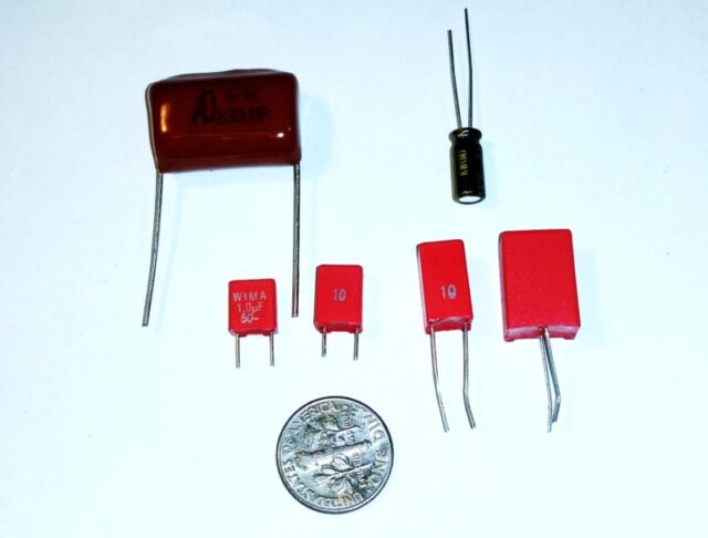
Here’s a picture of the new caps (red ones). They are left to right 1, 2.2, 4.7, and 10µƒ at 50v. Included is a 0.47µƒ polypropylene film cap, and a 1µƒ @ 50v. electrolytic.
They looked small enough that they might be able to drop right on to printed circuit boards. Next up on my bench was a 5000X that had been “traded in” on some other work we did. Great. There are not that many signal path caps in the 5000X, and it would be a quick and easy trial. You can see that the older 0.47µƒ film cap was just too large to use most anywhere, especially where a little electrolytic was already existing on the board with other components crowded around it.
Here’s the input board of the 5000X. All inputs go through this board and it serves as the phono preamp to boot. Each channel has a 1.5µƒ and two 10µƒ in the signal path. The 10’s are a little tight, and I replaced the 1.5µƒ with a 4.7, which dropped right in.
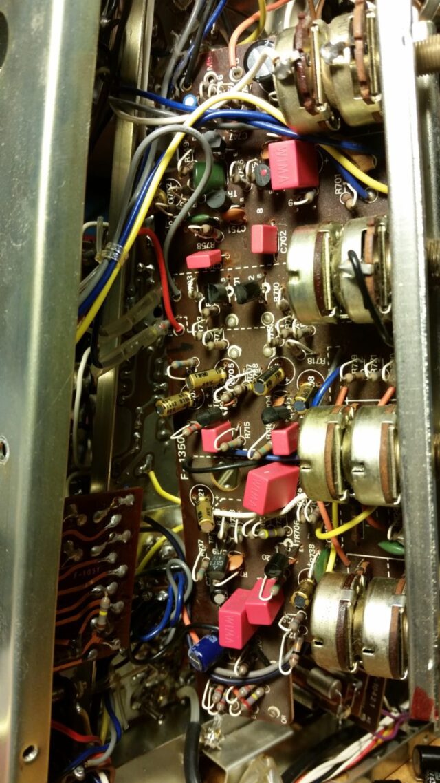
And here’s the tone board. Everything fit.
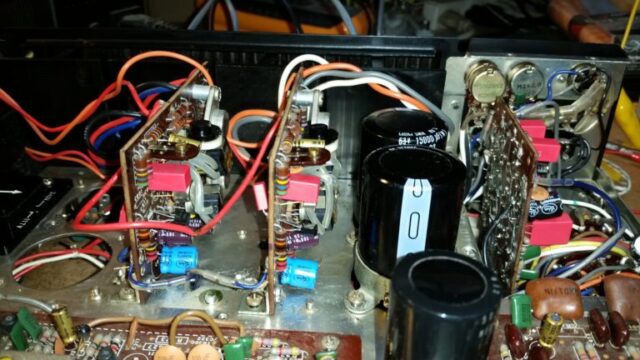
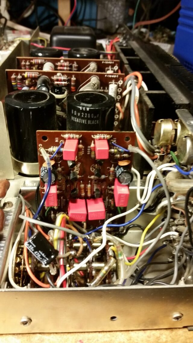
And here’s the output driver boards. 2 signal path caps on each. The input cap to this board, stock, is a 0.22µƒ mylar, replaced with a 1.0µƒ mylar. The other one is a high quality 2.2µƒ electrolytic, replaced by a 4.7µƒ mylar. The one soldered on the bottom of the board replaces the stock .22µƒ input mylar, which had leads a little too far apart to comfortably fit on the top. In other words the existing Mylar was too big for the 5X replacement to reach the through holes!
We have now done this on 4 different Sansuis, two early cap coupled amps, and two later complementary output amps.
On the two cap coupled amps, the result was stunning. We already do an upgrade to the big power supply cap and the two output caps in our normal restoration. Typically, we will upgrade the power supply cap to 4700µƒ at whichever voltage the amp uses, and we will upgrade the output cap, which is either a 1500µƒ or 2200µƒ to at least 10,000µƒ. We have gone as high as 15,000µƒ for the output cap.
When all the signal path caps were converted to mylar film caps on the 5000X, there was a general improvement in audio musicality and what I would call transparency. But… the most noticeable improvement was in the low end. I think this was due to the replacement of electrolytics in the tone control section.
Because of how tone controls are designed, caps of up to 10µƒ are required to make the bass control work. The film caps allow a high definition low end, using the bass control, something I have only heard with DC amps before.
The complementary style amps, (9090, 9001, most others after 1972) had the same sort of improvement, the improvements about equal in the tone controls and overall transparency. Justin commented when he did the first one, an 890db, that the film caps didn’t seem to make a lot of difference until he also added in the Differential Current Balance mod, which is the last thing we do with a restoration. Then he felt the difference was quite noticeable. I agreed with him. It’s kind of like the “Diff” mod brings the complementary style amps up to the level of quality that can be achieved with the upgraded early cap coupled amps, and then the film caps were a worthwhile addition.
At this point I am convinced that this is a true quality upgrade, and something we should offer, like we do the Differential Current Balance mod. I have struggled a bit with figuring out what to charge for this addition.
The new miniature mylar caps are quite expensive, costing us about $1-3 each. When we can buy in quantity, that price will come down some. The audio grade electrolytics (Nichicon UKW) we normally use in the signal path typically cost 8-10 cents each in 1000 qty lots. That’s a big increase in cost to add the mylars. We can eventually get the price down appreciably by buying in 1000 qty lots, but that will be a $8-10,000 investment in parts for us.
But fortunately, the number of signal path coupling caps is small. In the 5000X I did, there are 18 of them. However, in the 9001 there are 40 in the 4 amplifier channels, 18 on the quad processing boards, and 22 on the CD4 board, for a total of 80. The only way we can price this addition is to do it for each model. What we will do is just figure the cost for the caps, as there is very little increase in the labor required, since we are already changing out the caps anyway.
Our “Diff” mod is mainly a labor charge, as it takes a few hours to install and calibrate the parts. Most of the time is spent waiting for circuits to stabilize and then making adjustments. The parts are very inexpensive, you are paying for our expertise and time with that upgrade.
So for now, we will just quote a price for the mylars to go with each model. When we have done this for a while, we will get more structured about it.
Full LED Conversion
This is a modification we offer for receivers and tuners. We will rectify the power coming off the power supply board, converting the AC voltage to DC. From there, we will replace all incandescents with LEDs. We do our best to match the original color and brightness of the incandescents, but the real advantage with LEDs is that their lifespan is measured in the 10s of thousands of hours. We charge $145 for this service.
Click here to check out our gallery of completed LED mods..
Banana Plug Conversion
If you’re interested in getting banana plugs installed on any or all of your speaker outs, we can do it! We 3D print custom plates that fit perfectly in your unit and are spaced to fit banana plug jacks. We charge $130 per stereo pair for this service. Let us know which speaker systems you want converted!
If you would like to get your unit in our shop to be serviced, here’s a breakdown of what the process will look like:

Due us being a small shop with limited storage space for units, we use a queue system to hold your place in line while we work through our other restorations. After 2-4 months, we will contact you to let you know that we have space and you are free to ship your unit in to us. If you would like to get into the email queue, please send us an email at tech@qrxrestore.com with “Request For Service” in the subject field. Let us know your name and what unit you have and we can take it from there.
Once we’re ready for you to ship your unit in, we’ll email you to let you know. When it gets here, it’ll be another 2-4 months before we get it onto a bench and complete the restoration. After we fire up your unit, it’ll get calibrated and go through extensive testing. If we encounter anything out of the ordinary during this testing period, we’ll call you and update you on what’s happening with your unit and if we have to do any extra labor on it. Our bench fee is $110/hr for additional labor that falls outside of our standard restoration.

Once we have your unit looking and sounding great, we’ll send you an email with an invoice. After we receive payment, we will do one more final checkout of your unit to make sure everything is in proper order before we box it up and send it back for you to enjoy.