Recap and restore of the 9001
The Sansui QRX was built from late 1976 to 1979. It is the best of the Quadrophonic receivers, and also the most complex, with densely packed electronics and lots of pc boards, over 15 to be exact. There are roughly 174 electrolytic capacitors spread around on all these pc boards. Some are easily removed to work on. Others are attached with a multitude of wires, making it easier to recap those boards with them attached to the rest of the unit.
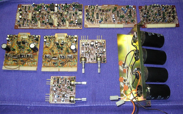
- The removable boards, from the 9001. Once removed they are relatively easy to work on.
The hardest part of the whole thing is what is called the 4 channel board, F2632. It is buried behind the front panel and has all the audio for the unit passing through it, controlled by the push button switches. In order to work on it, a small daughter board attached to the tops of the push switches has to be unsoldered and removed. This 4 channel board is a double sided pc board. That means there are foil traces on both sides of the board, and where they have to be joined, there are pass through connections. As is quite common on pc boards made in the 70’s, these pass through connections often become unreliable, and will cause intermittent problems.
On the 9001/8001,If you have an intermittent problem of almost any type, it usually is a pass through problem. The only real, long term solution is to pin these connections, This means take a short piece of wire, run it through the pass through hole, and solder each end to the actual trace on each side of the board. it’s a long and arduous process. Several of the pass-through are underneath or almost underneath other components such as the push switches, connectors, etc.
Here is a description of the fix from AudioKarma, Dec 2010
“Hi Anderslober,
Ye are a brave lad to tackle the most daunting receiver ever made, the mighty 9001!!
I’m working on another one right now, currently waiting for some transistors. I just redid the double sided board last week, and I took some pictures. First of all, don’t be tempted to just clean up the pass throughs and resolder them. I can tell you from experience that there will be one or two that will go bad again in short order. AND it is so much work to get to the board, well, once you have the blessed thing opened up and you are there, take your time and do it right. Some of them are really hidden, so make sure you find them all. One of them is part way under a nylon connector. You have to melt the connector with your iron, and then a razor blade will cut the melted part away. The trace extends under the connector.
See the pictures, and this is how you do it.
First suck up or wick up all the solder on the pass throughs. You should be left with a pretty big hole and a clearly uncovered rivet. Supposedly there are boards without rivets, but I haven’t seen one.
Then, with a scraping tool, carefully scrape back about 1/4-3/8″ of the green paint from the trace going to the pass through on each side. I made a tool from a small screwdriver, squaring off and sharpening the edges of it. You have to do every single one this way.
Put some solder on the scraped traces on both sides, being careful not to get so much of it on the rivet that the hole gets filled up again.
Take a short piece of tinned wire (I use clipped off cap leads) and bend it into an L shape. Tin a little glob of solder on the short side of the L.
Stick the L through a hole and holding the wire from the back side, angle it so that the tinned mini glob touches the trace. Then, just touch it with your iron so that the solder flows between the wire and the trace. You can be holding the wire on the back side with your fingers if you don’t linger too long with the iron.
Do all the holes on one side this way.
Go to the other side and with a small needle nose pliers, bend the wire down so that it touches the trace on this side. You can have the excess just pointing up away from the board.
With your soldering iron and solder, quickly solder the wire to the trace, and clip off the excess. Some traces will be very short, and I just solder the wire to the destination pad or pin, if it is going to a connector.
It does not matter whether you put solder in the hole, or not. You have now connected the two traces on opposite sides of the board. Note that there is one electrolytic under the daughter board.
Good luck, take your time. It’s a great amp/receiver/quad/preamp. After you get it all working, let me know and I can show you a simple mod that will make a decided improvement in sound quality.”
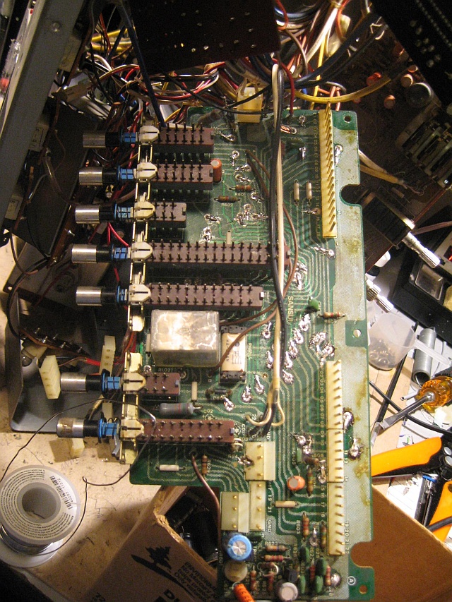
- Top of the 4 ch board, all repinned.
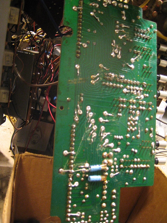
- The back side of the 4 ch board, all repinned.
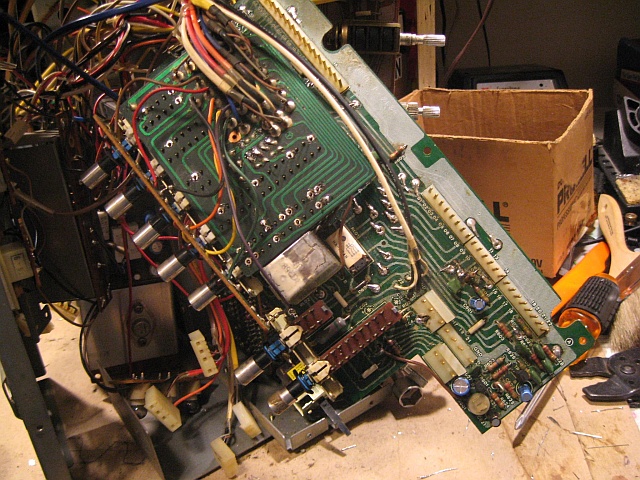
- The 4ch board with the daughter board resoldered on top of the pushbutton switches.
The only way to get to the 4 channel board is to disassemble the front panel. The panel is complex and once it is taken apart, the dial cord will have to be restrung. Recapping the rest of the unit is pretty straight forward. The four boards behind the front panel are the tough ones.
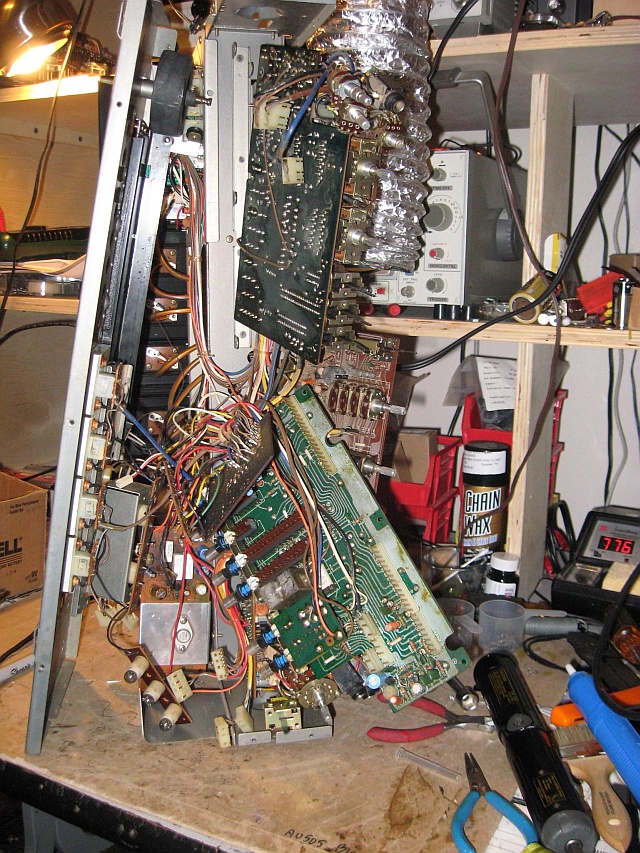
- The front panel of the 9001, disassembled and all the internals loose and ready to work on. Not for the faint hearted!!
This can all be done if you are careful and methodical in your work. Stand the unit up on its left side so that the weight of the power transformer is down. Then take the front panel apart and push it all to the left. Then you can get to the pc boards. This is the time to clean and lube all the front panel controls. We use a product called Corrosion X. It cleans and lubricates in one application. We like it because it seems to last much longer than the separate cleaners and lubes available.
