There’s a lot of info on this page, in no particular order. When we learn more, or want to add new stuff we just sort of add it to this page. So, you might want to skim through to find the info you are interested in.
What does a restoration consist of? For a list of steps, go here.
A lot of people contact us and ask how to go about buying a used unit. This is tricky, at best, with ebay being the usual source. These units are rare and the chances of you running across one at a 2nd hand store, or a garage sale, are slim. It does happen though. Here’s some tips on what to look for, here.
Tricks and Tips
We make a concerted effort to help those who have decided to restore their own QRX. Basically, if a persona has the skills to do this, they are probably not going to have us do it. We have a lot of experience though, and hopefully this site will help with that. Here’s a few things we have learned, mostly the hard way, about working on these monsters, here. We also sell some very hard to find parts for these units. Check out our parts page, here.
Recap and restore of the 9001
The Sansui QRX was built from late 1976 to 1979. It is the best of the Quadrophonic receivers, and also the most complex, with densely packed electronics and lots of pc boards, over 15 to be exact. There are roughly 174 electrolytic capacitors spread around on all these pc boards. Some are easily removed to work on. Others are attached with a multitude of wires, making it easier to recap those boards with them attached to the rest of the unit.
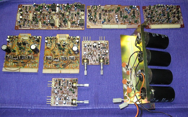
The removable boards, from the 9001. Once removed they are relatively easy to work on.
The hardest part of the whole thing is what is called the 4 channel board, F2632. It is buried behind the front panel and has all the audio for the unit passing through it, controlled by the push button switches. In order to work on it, a small daughter board attached to the tops of the push switches has to be unsoldered and removed. This 4 channel board is a double sided pc board. That means there are foil traces on both sides of the board, and where they have to be joined, there are pass through connections. As is quite common on pc boards made in the 70’s, these pass through connections often become unreliable, and will cause intermittent problems.
On the 9001/8001,If you have an intermittent problem of almost any type, it usually is a pass through problem. The only real, long term solution is to pin these connections, This means take a short piece of wire, run it through the pass through hole, and solder each end to the actual trace on each side of the board. it’s a long and arduous process. Several of the pass-through are underneath or almost underneath other components such as the push switches, connectors, etc.
Here is a description of the fix from AudioKarma, Dec 2010
“Hi Anderslober,
Ye are a brave lad to tackle the most daunting receiver ever made, the mighty 9001!!
I’m working on another one right now, currently waiting for some transistors. I just redid the double sided board last week, and I took some pictures. First of all, don’t be tempted to just clean up the pass throughs and resolder them. I can tell you from experience that there will be one or two that will go bad again in short order. AND it is so much work to get to the board, well, once you have the blessed thing opened up and you are there, take your time and do it right. Some of them are really hidden, so make sure you find them all. One of them is part way under a nylon connector. You have to melt the connector with your iron, and then a razor blade will cut the melted part away. The trace extends under the connector.
See the pictures, and this is how you do it.
First suck up or wick up all the solder on the pass throughs. You should be left with a pretty big hole and a clearly uncovered rivet. Supposedly there are boards without rivets, but I haven’t seen one.
Then, with a scraping tool, carefully scrape back about 1/4-3/8″ of the green paint from the trace going to the pass through on each side. I made a tool from a small screwdriver, squaring off and sharpening the edges of it. You have to do every single one this way.
Put some solder on the scraped traces on both sides, being careful not to get so much of it on the rivet that the hole gets filled up again.
Take a short piece of tinned wire (I use clipped off cap leads) and bend it into an L shape. Tin a little glob of solder on the short side of the L.
Stick the L through a hole and holding the wire from the back side, angle it so that the tinned mini glob touches the trace. Then, just touch it with your iron so that the solder flows between the wire and the trace. You can be holding the wire on the back side with your fingers if you don’t linger too long with the iron.
Do all the holes on one side this way.
Go to the other side and with a small needle nose pliers, bend the wire down so that it touches the trace on this side. You can have the excess just pointing up away from the board.
With your soldering iron and solder, quickly solder the wire to the trace, and clip off the excess. Some traces will be very short, and I just solder the wire to the destination pad or pin, if it is going to a connector.
It does not matter whether you put solder in the hole, or not. You have now connected the two traces on opposite sides of the board. Note that there is one electrolytic under the daughter board.
Good luck, take your time. It’s a great amp/receiver/quad/preamp. After you get it all working, let me know and I can show you a simple mod that will make a decided improvement in sound quality.”
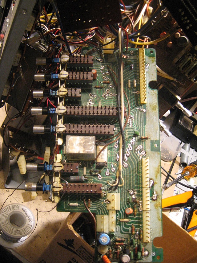
Top of the 4 ch board, all repinned.
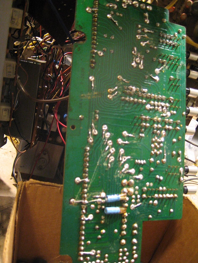
The back side of the 4 ch board, all repinned.
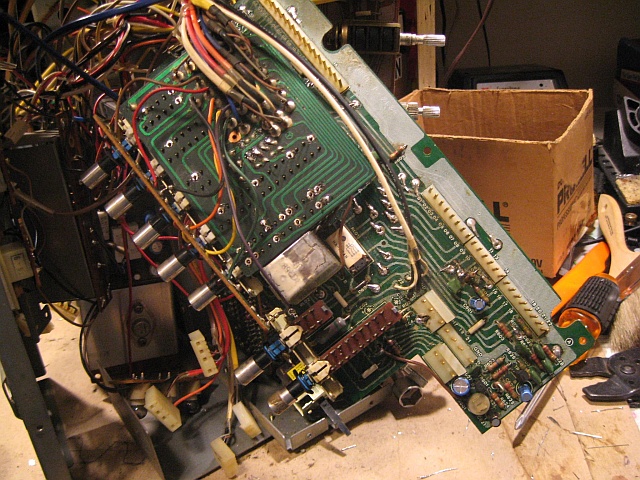
The 4ch board with the daughter board resoldered on top of the pushbutton switches.
The only way to get to the 4 channel board is to disassemble the front panel. The panel is complex and once it is taken apart, the dial cord will have to be restrung. Recapping the rest of the unit is pretty straight forward. The four boards behind the front panel are the tough ones.
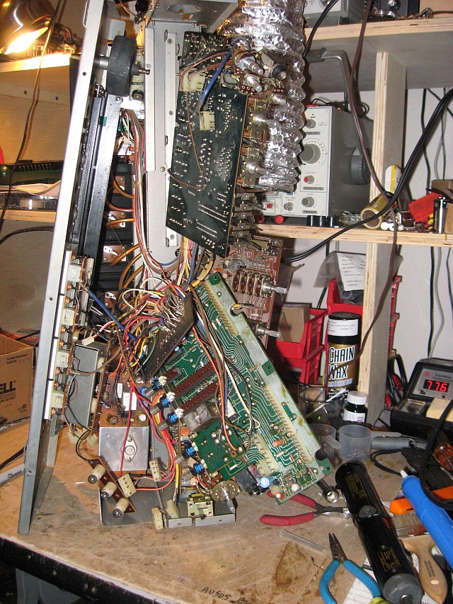
The front panel of the 9001, disassembled and all the internals loose and ready to work on. Not for the faint hearted!!
This can all be done if you are careful and methodical in your work. Stand the unit up on its left side so that the weight of the power transformer is down. Then take the front panel apart and push it all to the left. Then you can get to the pc boards. This is the time to clean and lube all the front panel controls. We use a product called Corrosion X. It cleans and lubricates in one application. We like it because it seems to last much longer than the separate cleaners and lubes available.
Here’s a list of the electrolytic caps needed for the recap. Note that the ones at the end of the list, marked BP, are bipolar capacitors. We use Nichicon UKW’s or, when not available, UKT’s. these caps are designed specifically for audio and they do sound very good. It is hard to tell the difference between them and a good film cap.
If you are up to a task such as this, you don’t need any instructions from us as to how to do it. Turning on the unit for the first time can be daunting, though, as the receiver will probably come up in protection, due to changing out the fusible resistors. Here are a couple postings that describe bringing up a 9001 that has just had 200 parts changed inside.
Posting from Audiokarma, Dec 2010
Anderslober,
Hold on, slow down. Starting up one of these beasts for the first time, when you haven’t had it going for a while, and you’ve changed a couple hundred parts inside, well, it’s a damn stressful and anxiety ridden experience. I just went through this last nite and this morning. It’s stressful.
I actually had an almost a similar experience when I turned this one on for the first time. I had not connected two wires from the power supply to the big capacitor assembly, sitting right over top of the power supply. There’s a relay circuit that waits for the caps to get charged before anything else happens.
So, let’s talk about a few things first.
The big caps can be a concern. Usually they are ok, but I had one 9001 with all 4 of them bad. If you’re concerned about them, I have a method of checking them that uses a 9v battery, a multi meter and a 1k ohm resistor. let me know if you want to check them.
Check and double check that all your connections to the power supply board are correct. Every single one of these, I have done, I do something wrong with hooking up all those wires. There are labels on the PC board that even list color of wire, but they are not absolutely correct.
You have mentioned several times about worrying about transistors being bad. There’s a very simple way to check transistors using the diode function on your multimeter, most DMM’s have that. google “checking transistors” and play with doing it until you feel confident you can check them. Then check any trans you are worried about.
Something that is very important is to change out the fusible resistors on the 2624 power driver boards. These have to be changed. it’s simple to do. There are 6 4.7 ohm, 4 10 ohm, 4 150 ohm, and 2 180 ohm resistors per board. They have gotten hot and have drifted way off in value. Every 9001 I have seen has this problem. They are the light bluish resistors standing up above the board so that if they burn up, they will not burn the board. You can replace them with 1/2 watt metal film resistors.
Here’s how I start up. This is a complex beast and if something goes wrong, you want to catch it right away.
Make a stereo 1/4″ phone plug up with wires coming from the two hot connections. We will use this to set the output level at no signal to less than 10 mv.
Set all the controls to play two channel sound from the AUX input. tone controls at middle, volume all the way down. I hook an IPOD up to the aux and get it playing.
Have some speakers you don’t care too much about for the front stereo out. If you have two more, have them ready for the rear out.
Plug a pair of headphones (again, cheap ones) into the front jack. We’re going to use headphones, because if the protection does not come off, the speakers won’t play, but if the amplifier still works, we can hear it through the headphones, the protection interrupts speakers, not the phones. The headphone out goes through a 220 ohm resistor, so it is pretty safe for the phones. I have had an out put at 48v, and the protection relay did not close, but it didn’t blow the phones either.
This part is really important. We want to set the bias at minimum, so that when the amp starts up, and before you can get to each of the individual channels, the bias is the lowest possible with the least chance of getting into some sort of thermal runaway condition.
First you must determine which kind of 2624 driver board you have. There are two types. One is called the transistor bias version and the other the diode bias version. Here’s how you tell. At the bottom of the board there are 4 heatsinks. Two of them have devices mounted on top with wires running down to the pc board. If these devices have 3 wires, you have the transistor bias version. If they have 2 wires, you have the diode bias version.
For the transistor bias version adjust VR3 full clockwise, VR4 full counter clockwise.
For the diode bias version adjust VR3 full counter clockwise, VR4 full clockwise.
On both boards leave VR1 and VR2 alone. They are the offset adjustment trimmers and are most likely to be closest in their current position.
NOW, check everything over again. And if you feel ok, not too stressed, with the headphones on, turn it on.
Volume all the way down, just look and listen for a couple seconds. Everything should lite up. If it does, good. If you aren’t hearing anything bad, turn up the volume control. If you hear music, great. The protection works by detecting any DC that it doesn’t like on any of the 4 outputs. If any one of them is bad, all of the speaker outputs will be interrupted. This is why the headphones, cause you can still hear music even if protection is on.
With your multimeter measure the voltage on the little power supply board behind the tone controls, 2nd terminal down on the right. It is marked “01” You should read 25v here. There’s a pot on this board that you adjust for 25v. This 25v powers the 2 quad decoder boards and is very important. Adjust it slowly and carefully to 25v. Don’t adjust it up or down away from 25v. cause you can blow the chips on the quad boards. Trust me, I’ve done it.
If you’ve made it this far, unplug your phones and plug in the stereo plug you made with wires coming out of it. With your DMM measure the voltage on the left and right front. On the 2624 power output driver board, you then adjust this voltage to be within + or – 10 mv of zero volts on the output for left and right. adjust Vr1 and Vr2 and read the voltage with your DMM. Vr1 and Vr2 are the pots at the top of the driver board on either side of the input connector. Turn the volume all the way down when you do this adjustment. Then plug the 1/4″ plug into the back channels and do the same. If all your voltages are at spec, great. If not, don’t despair. This is about the only way you can measure speaker output voltages easily, if the unit is in protection
The 9001 I brought up this morning was in protect, one of the output voltages was way off of zero.
If they are right, you can hook up the speakers and see if they play, and the unit is out of protection.
And here is more from AudioKarma, Jan 2011
Yes, yes, and yes. (love it) That’s correct, when the unit is in protect, all 4 speaker outputs are disconnected from the amplifiers. The phones are still hooked up, though. So you can measure the outputs there. You also can go and probe around on the protect circuit board, but the phones output is so much easier.
And did you listen with headphones? This is very important. If you can hear audio on the phones, it means that audio is making it’s way all the way through your 9001 to the outputs. It’s a basic test of the system.
Now, if you get nasty noises on the headphones, like a buzz or humm, crackling etc., there’s a simple test to figure out where it’s coming from. Does it follow the volume control? If yes, it is before the output section. If it doesn’t follow the volume, simply disconnect the input connector to the 2624 driver boards. If the noise is still there on the phones, it means the noise is coming from the 2624s, if not, it’s coming from the rest of the unit (after the volume control). The input connector is the one on the top of the 2624 boards.
If you get no audio on the phones, with or without the nasties, then you should also check the power supply voltages at some point.
If you can, bring the dc offset within range on the outputs. Then it’s time to set bias. You should probably do this sooner than later, as you said the heat sinks get warm. Be very careful doing this. Turn the unit off, hook up your meter to the fuse flange, then turn it back on. If you still have the ancient meter around with the actual needle, it’s great for checking bias. Set it at a higher range than you need and as you get the bias in range, switch to a more appropriate (lower) amperage range on the meter.
So let’s make it step by step.
1. listen for audio on the headphones, both front and rear channels. The rears have to be selected with the speaker select switch by going to 4 ch mode. If you have audio, great, any channels without indicate problems.
2. Read DC offset on the phones outputs (volume all the way down), and adjust to zero (+ or – 10mv) using the VR1, 2 on the 2624 boards, fronts and rears. Note any voltages and their polarity for channels that will not come in range.
3. The combination of which channels have audio and which channels you can adjust to zero, tell us the condition of the unit.
4. If there are nasty noises, can you turn them up and down with the volume control? If you can, the problems are before the output section. If not, disconnect the inputs to the 2624 boards and see if the noise goes away. You may have to do this before step 2. If the noise goes away it indicates that the source is before the power outputs and after the volume control. Then go back to step 2.
5. Adjust bias in any channels that will come in range for offset and do not have nasty noises.
6. At this point we have a condition report on the unit. Report here and we will move on to whatever is next. If everything is working, I’m sure you will just continue on checking things out. In any case, let us know. If you got all the offsets in range, and the bias set, then the unit should come out of protect mode and the speakers should work. You have to unplug the phones for the speakers to work.
7. if none of the above worked, make some voltage measurements on the power supply board and report that to us here.
Sorry, I should have made you a step by step earlier. We will get there, though.

This is probably the most beat up 9001 we have seen. It has been dropped, scratched, left in the damp to rust, and many other sins. The panel cleaned up nicely, but the plastic panel behind the glass, with all the writing on it was either glued, or had solvent leaked on it. All the writing and numbers are squiggly. Most people smile or laugh when they see it for the first time. Functionally it is now perfect and serves as our shop stereo/reference unit/test bed. The build quality of these old units is absolutely amazing. If manufactured today, they would cost $4000-5000.
List of electrolytics for the 9001
| 6v | 10v | 16v | 25v | 35v | 50v | 63v | 80v | ||
| 0.22 | 2 | ||||||||
| 0.47 | 5 | ||||||||
| 1 | 27 | ||||||||
| 1.5 | 7 | ||||||||
| 2.2 | 10 | ||||||||
| 3.3 | 13 | 8 | 8 | ||||||
| 4.7 | 11 | 2 | |||||||
| 10 | 13 | 8 | 8 | ||||||
| 22 | |||||||||
| 33 | 1 | ||||||||
| 47 | 3 | 2 | 2 | ||||||
| 100 | 3 | 3 | 2 | 4 | 4 | ||||
| 220 | 4 | 3 | 3 | 2 | 3 | ||||
| 330 | 6 | ||||||||
| 470 | 5 | 1 | |||||||
| 1,000 | 2 | ||||||||
| 10,000 | 4 |
| bipolars | 2 | 1@50v |
| 8 | 4.7@80v | |
| 4 | 10@50v | |
| 4 | 47@6.3v |
Fusible Resistors ½ watt metal film
| 12 | 4.7 ohm |
| 4 | 10 ohm |
| 8 | 150 ohm |
| 4 | 180 ohm |
